04 Design & Implementation
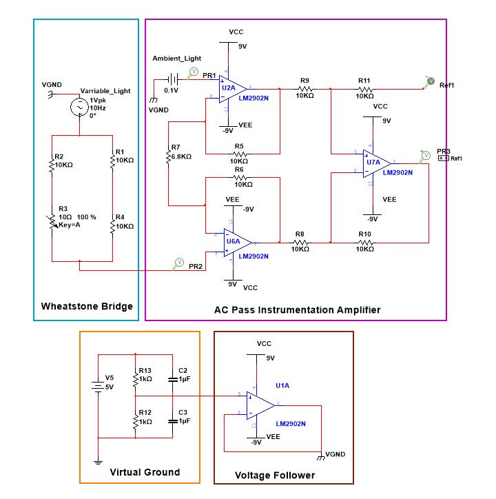
Complete Circuit Schematic - All Stages
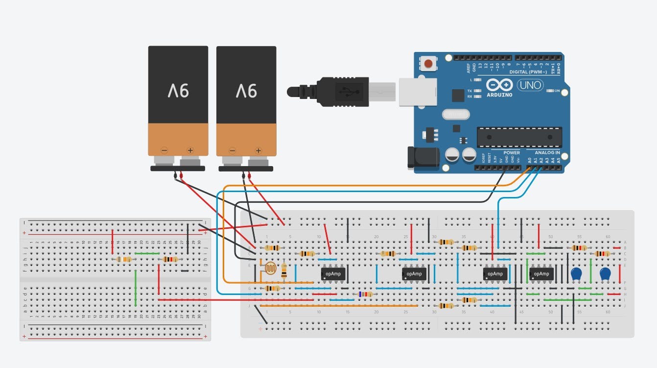
Fritzing Wiring Diagram with Arduino UNO
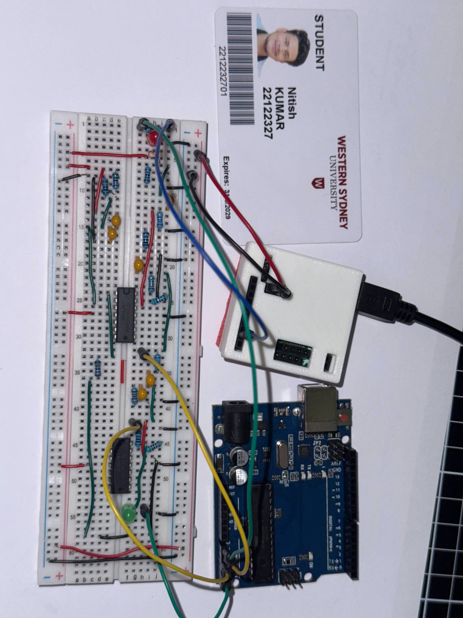
Implemented Circuit on Breadboard
Multi-stage analog signal processing system for optical communications. Utilizes dual-LDR differential sensing, instrumentation amplifier, cascaded bandpass filters, and output buffering to recover clean signals from noisy environments across 5Hz-200Hz bandwidth.
Optical communication systems face significant noise challenges from ambient light interference. This project demonstrates advanced signal conditioning techniques to extract a weak LED-modulated signal from a noisy environment using differential sensing and multi-stage filtering.
A dual-LDR configuration captures both signal+noise (A0) and noise-only (A1). A differential amplifier subtracts A1 from A0, eliminating common-mode interference. Cascaded active and passive bandpass filters then isolate the 5Hz-200Hz target frequency while rejecting out-of-band noise.
Part of ELEC7008 Instrumentation & Measurement at Western Sydney University. Applies fundamental concepts in sensor interfacing, noise rejection, op-amp circuits, active/passive filters, and signal chain design for real-world measurement systems.
Successfully implemented differential amplifier architecture to cancel common-mode ambient light interference. The dual-LDR configuration captures noise separately and subtracts it from the signal path, dramatically improving signal-to-noise ratio in the presence of strong environmental interference.
Designed and tuned cascaded bandpass filter stages (active → passive) to isolate 5Hz-200Hz target frequency band. The combination of active filtering for gain control and passive filtering for final cleanup provides superior out-of-band rejection while maintaining signal integrity.
Integrated all stages from sensor interfacing through signal conditioning to buffered output. Arduino UNO data acquisition at multiple test points (A0, A2, A3) validates progressive signal improvement through each processing stage, confirming successful recovery of the clean signal.
Frequency Range: 5Hz - 200Hz
Signal Source: LED (Labradog modulated)
Sensors: Dual LDR array
Coupling: AC coupled
Supply: ±9V (single supply with virtual ground)
Op-Amps: LM2902N (Quad)
Sensors: 2× LDR photoresistors
MCU: Arduino UNO
Power: 2× 9V batteries
Passive: Resistors, capacitors, LEDs
Topology: Multi-stage signal chain
Noise Rejection: Differential amplifier
Filtering: Active + Passive BPF
Output: Unity-gain buffer
Testing: Arduino multi-point acquisition