04 Build Gallery
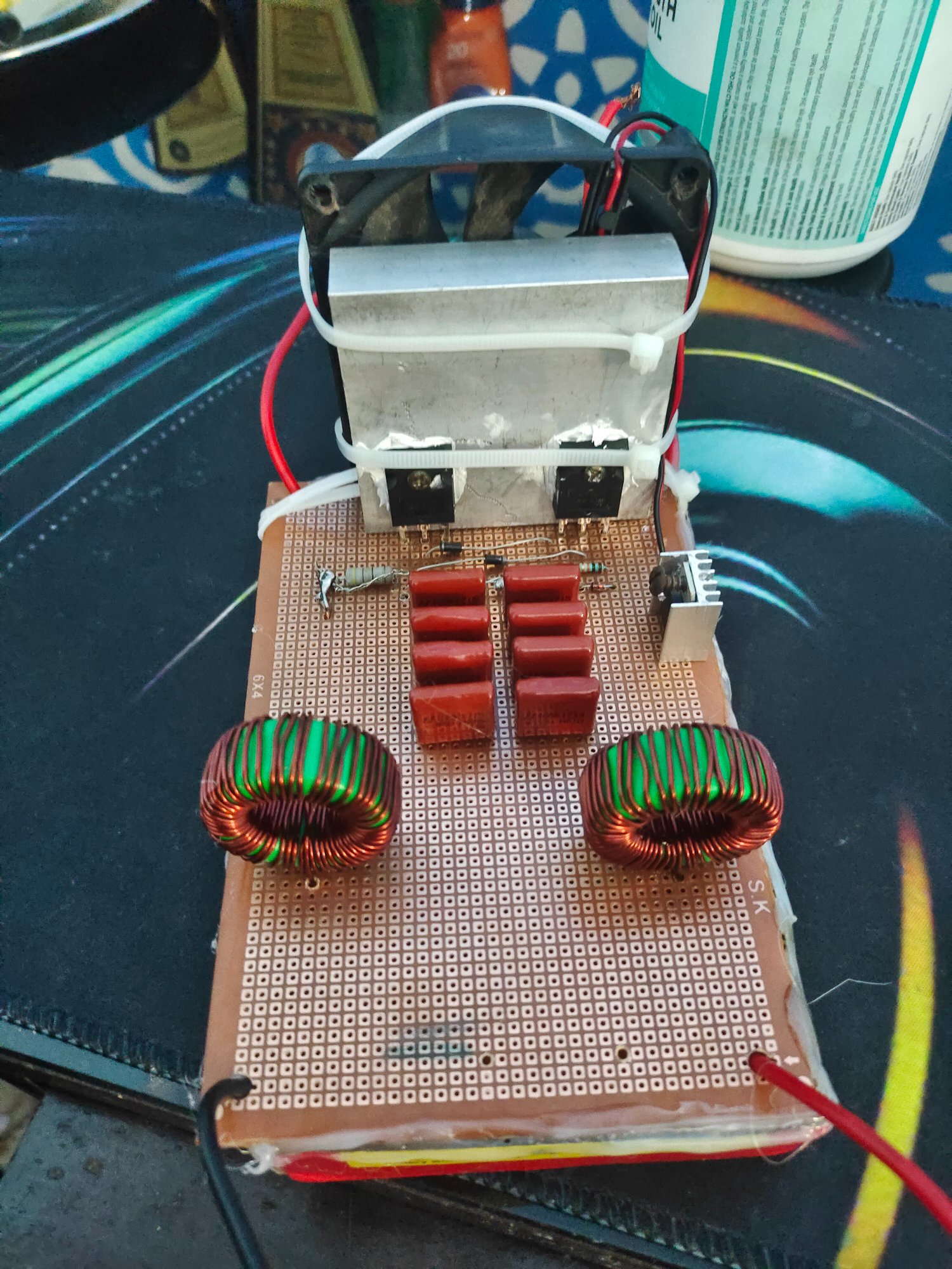
Complete High-Frequency Inverter Assembly
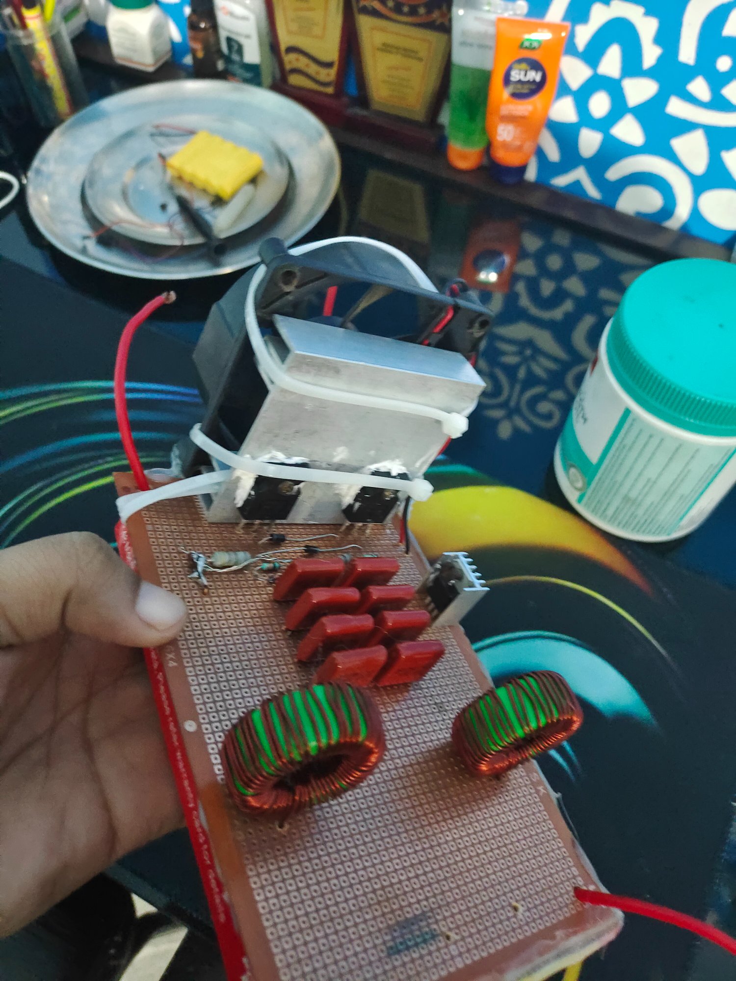
Circuit Detail - Toroidal Inductors & Components
Custom-built power inverter circuit generating 15V high-frequency AC square wave from DC input. Features MOSFET switching, toroidal inductors for filtering, and transformer-based voltage conversion.
A DC-AC inverter converts direct current (DC) to alternating current (AC) through high-frequency switching. This project demonstrates fundamental power electronics principles including MOSFET switching, magnetic energy storage, and waveform generation.
Power MOSFETs rapidly switch DC input to create a pulsed waveform. Toroidal inductors filter and smooth the output while storing magnetic energy. A transformer provides isolation and voltage conversion to generate a clean 15V high-frequency square wave output.
DC-AC inverters are essential in solar systems, UPS backup power, electric vehicles, motor drives, and portable power supplies. This prototype demonstrates the core principles used in modern inverter technology.
MOSFET switching converts the DC input into a high-frequency AC waveform. Toroidal inductors and the transformer stage support filtering, magnetic energy transfer, and voltage conversion.
The build demonstrates waveform generation through fast switching and shows how frequency, duty cycle, magnetic components, and output loading affect practical inverter behavior.
Hand-built on perfboard with available components, demonstrating practical understanding of power electronics assembly, stage-by-stage testing, soldering, and safe low-voltage validation.
Voltage: 15V AC
Waveform: Square Wave
Frequency: High-Frequency
Type: AC Output
Switching: Power MOSFETs
Inductors: Dual Toroidal
Capacitors: Electrolytic Bank
Transformer: Isolation Type
Validation: Low-voltage prototype test
Topology: Push-Pull/H-Bridge
Construction: Perfboard
Status: Operational